How to prepare artwork for contour cut products
Interested in joining the world's leading print on demand platform?
Learn how to prepare print-ready artwork for custom-shaped products like wall stickers, furniture decals and Exoboard.
Get started with our step-by-step guide, or get your file checked by our support team before you submit it.
Building an integration or automated pipeline? Skip straight to the technical reference.
What is contour cutting?
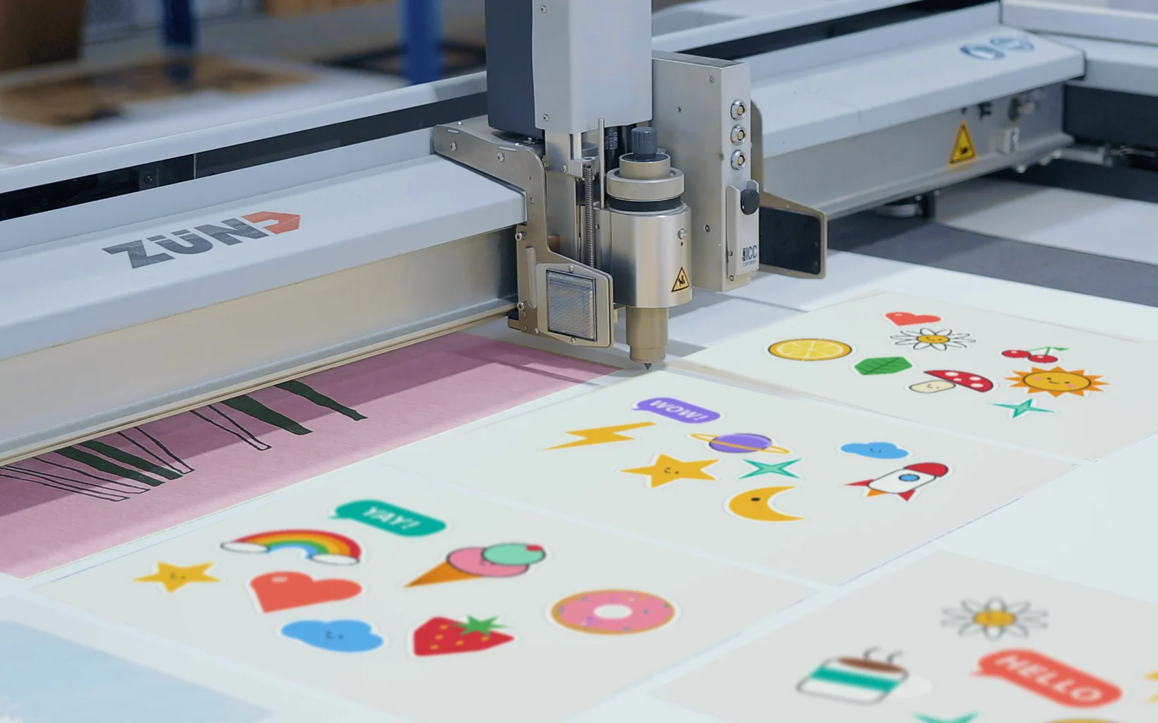
Contour cutting is a print finishing technique in which a printed material is trimmed to a custom shape using a precision cutting machine. Rather than producing a standard rectangle, the cutter follows a defined path – called a cut line or cut contour – to produce any outline the design requires. The result is a finished product whose shape matches the artwork exactly.
Which Prodigi products support contour cutting?
Contour cutting is available for the following print on demand products:
What should your contour cut file include?
Your artwork and cut path must be combined into a single-page PDF, with both elements kept on separate layers. Here’s how to prepare your file correctly.
- Layer 1 – printed design
- Your artwork: images, backgrounds and design elements that appear on the finished product.
- Layer 2 – cutting instruction
- The cut path: a named vector path telling the cutter where to cut. It must not print as a visible border.
Both belong in the same file. Keep them on separate layers and don’t flatten or merge them.
Prepare your file in five steps
Follow these in order, then use the pre-submission checklist below before submitting your PDF.
- Create your artwork. Work at the finished product size, at 1:1 scale. Use RGB colour mode and at least 300 DPI for raster content.
- Draw the cut path. Use a smooth vector path, with a 1pt stroke and no fill. Keep the path simple where possible.
- Name the spot colour
CutContour. The name is case-sensitive and must match exactly. Define the swatch as a spot colour, not a process colour. In Adobe Illustrator, set Colour Type to Spot Color. - Set overprint and layer order. Set the cut path to overprint and place it on the top layer, above the artwork.
- Add bleed and export. Extend the artwork at least 1.5mm beyond the cut path on all sides. Export a single-page PDF with vector data and spot colours preserved.
Understanding spot colours and bleed
The cutter looks for the spot colour name CutContour, not the colour’s appearance. Magenta is a useful display convention, not the cutting instruction itself.
CutContour display colour
HEX: #FF00FF
RGB: 255, 0, 255
CMYK: 0, 100, 0, 0
Common mistake. A magenta line defined as a process colour may print as a visible pink outline instead of being recognised as a cut instruction.
1.5mm
Minimum bleed on every side
Extend your colour or image beyond the cut path to avoid a white halo.
±1mm / ±0.5mm
Print/cut alignment
Small variations in alignment can occur during production, which is why artwork must extend beyond the cut path.
What about transparent areas?
Transparent areas show the substrate colour – white on most products. They are not see-through unless you’ve selected a clear substrate. White areas can simply show the material rather than printed white ink.
Why simplify the cut path?
Complex shapes with many curves and nodes can slow cutting and increase the risk of errors on fine details. Use your design software’s simplify-path feature where possible.
Document and export settings
Document settings
| Document setting | Required value |
| File format | Single-page PDF |
| Colour mode | RGB artwork |
| Raster resolution | Minimum 300 DPI |
| Scale | 1:1 – cut path at the intended finished product size, with artwork extending beyond it for bleed |
Export settings
| Export setting | Required value |
| PDF compatibility | PDF/X-4 preferred, or PDF 1.6+ |
| Preserve vector data | On |
| Downsample images | Off, or Minimum 300 DPI |
| Flatten transparency | Off |
| Include spot colours | On |
Don’t flatten or rasterise on export. The CutContour path must remain an editable vector path with its spot colour intact.
Troubleshooting common mistakes
- A pink outline appears on the printed product
- Check that the cut path uses a spot colour rather than a process colour, and that its name is exactly
CutContour. Any spelling differences, extra spaces or incorrect capitalisation can prevent the cutter from recognising it. - A white halo appears around the edge
- Add at least 1.5mm bleed beyond the cut path on all sides.
- The cutter ignores the cut line
- Check that the path is a vector, not a rasterised outline, and that spot colours are preserved in the PDF.
- The cut lands in the wrong place
- Keep artwork and cut path in the same PDF at 1:1 scale, without moving or scaling them separately.
- The file is rejected or the cut is the wrong size
- Submit a single-page PDF at 1:1 scale, with the cut path at the intended finished product dimensions. Avoid scaling the artwork or cut path during export.
- The path is missing after export
- Don't merge or flatten layers. Preserve vectors, spot colours and overprint settings.
Pre-submission checklist
Tick off each requirement before uploading your file.
- Single-page PDF at 1:1 scale, with the cut path at the intended finished size
- Colour mode is RGB, resolution 300 DPI minimum
- Artwork extends at least 1.5mm beyond cut line on all sides
CutContouris a vector path – not rasterised- Spot colour named exactly
CutContour CutContouris stroke only – 1pt, no fillCutContouris set to overprintCutContouris on the top layer- Layers not flattened or merged
- No transparent areas expected to appear clear (unless clear substrate)
- PDF exported with vectors preserved & spot colours included
Size and shape limits
Very small shapes, sharp corners and narrow protrusions can be difficult to cut cleanly. Keep these minimums in mind when designing your shape.
15mm
Minimum product dimension
Smaller items are difficult to handle and weed.
1.5mm
Minimum inner corner radius
For vinyl and paper products.
3mm
Minimum inner corner radius
For foamboard products.
5mm
Minimum inner corner radius
For Dibond (aluminium composite).
3mm
Minimum width of any narrow protrusion
Thinner than this may bend or break.
Got a question?
Our support team can check your file before submission or help troubleshoot your artwork.
Technical reference
Technical guidance for developers and AI agents on generating contour cut print files programmatically. This section translates the guide above into executable specifications.
Canonical PDF specification
| Property | Required value |
| Format | PDF/X-4, single page |
| Colour space | RGB (artwork) + Separation (cut path) |
| Resolution | ≥ 300 DPI for all raster content |
| Scale | 1:1 – cut path at the intended finished product dimensions, with additional space for bleed where required. No scaling on export |
| Bleed | Artwork extends ≥ 1.5mm beyond the cut path on all sides |
| Cut path type | Vector path – not rasterised, not a clipping mask |
| Cut path colour | PDF Separation colour space, name = CutContour |
| Cut path stroke | 1pt, no fill |
| Cut path overprint | true (OPM 1) |
| Cut path z-order | Topmost content stream element |
PDF separation colour space
The RIP identifies the named Separation channel CutContour. Its DeviceRGB alternate colour space is a screen-preview fallback, not a process-colour cut instruction.
% Colour space definition
/CutContourCS [/Separation /CutContour /DeviceRGB
  << /FunctionType 2 /Domain [0 1]
     /C0 [1 1 1] /C1 [1 0 1] /N 1 >>]

% In the content stream, to stroke with this colour:
/CutContourCS CS   % Set stroke colour space
1 SC               % Set separation tint to 100%
1 w                % 1pt line width
true OC            % Overprint control
... path operators ...
S                  % Stroke (not fill)
Approach 1: ReportLab
Best for programmatic generation where you control the full pipeline. For complex shapes, replace rect() with moveTo(), lineTo() and curveTo() calls, or convert an SVG path to PDF path operators.
from reportlab.lib.units import mm
from reportlab.lib.colors import CMYKColorSep
from reportlab.pdfgen.canvas import Canvas

# Define the cutter guide spot colour
cutter_spot = CMYKColorSep(
    0, 1, 0, 0,  # visual fallback (magenta)
    spotName='CutContour',
    density=1
)

# Create canvas at exact product size + bleed
product_w, product_h = 85 * mm, 55 * mm  # e.g. card
bleed = 1.5 * mm
canvas_w = product_w + 2 * bleed
canvas_h = product_h + 2 * bleed

c = Canvas('output.pdf', pagesize=(canvas_w, canvas_h))

# 1. Draw artwork (full canvas incl. bleed)
c.drawImage('artwork.png', 0, 0, width=canvas_w, height=canvas_h)

# 2. Draw cutter guide on top
c.setStrokeColor(cutter_spot)
c.setLineWidth(1)  # 1pt
# Rectangle cut path offset by bleed amount
c.rect(bleed, bleed, product_w, product_h, stroke=1, fill=0)

c.save()
Approach 2: SVG to PDF
When artwork originates as SVG, convert to PDF first then inject the spot colour definition in a post-processing step. This keeps design tooling simple and handles the PDF spot colour requirement separately.
Y-axis flip
SVG origin is top-left, Y increases downward. PDF origin is bottom-left, Y increases upward. Flip when converting: pdf_y = page_height - svg_y
# Step 1: Generate SVG with two layers
# - Artwork layer: standard RGB fills and strokes
# - Cut layer: path with class="cut-contour"
#   (use a placeholder colour, e.g. #FF00FF)

# Step 2: Convert SVG to PDF (e.g. via CairoSVG,
# Inkscape CLI, or headless browser)
import cairosvg

cairosvg.svg2pdf(url='design.svg', write_to='intermediate.pdf')

# Step 3: Post-process PDF to replace the RGB magenta
# path with a Separation spot colour. This requires
# manipulating PDF content streams directly (see the
# pikepdf example below).
Approach 3: pikepdf
Use when receiving customer-supplied PDFs or output from design tools that cannot natively create spot colours. Also the recommended approach for the SVG pipeline’s post-processing step.
import pikepdf

pdf = pikepdf.Pdf.open('input.pdf')
page = pdf.pages[0]

# Define Separation colour space for CutContour
sep_cs = pikepdf.Array([
    pikepdf.Name('/Separation'),
    pikepdf.Name('/CutContour'),
    pikepdf.Name('/DeviceRGB'),
    pikepdf.Dictionary({
        '/FunctionType': 2,
        '/Domain': pikepdf.Array([0, 1]),
        '/C0': pikepdf.Array([1, 1, 1]),
        '/C1': pikepdf.Array([1, 0, 1]),
        '/N': 1
    })
])

# Add to page resources
if '/ColorSpace' not in page['/Resources']:
    page['/Resources']['/ColorSpace'] = pikepdf.Dictionary()
page['/Resources']['/ColorSpace']['/CutContourCS'] = sep_cs

# Now rewrite content stream to use /CutContourCS
# for any path that was previously #FF00FF
# (implementation depends on content stream parsing)

pdf.save('output.pdf')
AI agent prompt template
The following system prompt can be passed to an AI agent or LLM to produce a conformant contour cut file.
Create a cut path at the intended finished product dimensions, at 1:1 scale. Extend the artwork at least 1.5mm beyond the cut path on all sides to provide bleed. Add a vector path named "CutContour" as a Separation spot colour with 1pt stroke, no fill, set to overprint. Place the cut path on the topmost layer. Export as a single-page 300 DPI RGB PDF preserving vectors and spot colours (PDF/X-4). The cut path must not print — it is a machine instruction. The spot colour name must be exactly "CutContour" (PascalCase, no spaces or hyphens). Any deviation will cause the RIP to treat it as printable artwork.
Validation
Before submitting a generated file – whether it’s been produced by a script or an AI agent – verify the following programmatically.
- PDF has exactly one page
- Page media box accommodates the cut path at the intended finished product dimensions, plus at least 1.5mm of artwork bleed on all sides
- PDF contains a Separation colour space with the name
CutContour - At least one path uses the
CutContourcolour space and is stroked (S), not filled (f/F) - All raster images have resolution ≥ 300 DPI at 1:1 output size
- Cut path bounding box is inset from media box by ≥ 1.5mm
- No path segments have a radius below the minimum for the target substrate
import pikepdf

def validate_contour_cut_pdf(path):
    pdf = pikepdf.Pdf.open(path)
    errors = []

    # Check page count
    if len(pdf.pages) != 1:
        errors.append(f'Expected 1 page, found {len(pdf.pages)}')

    page = pdf.pages[0]
    res = page.get('/Resources', {})
    cs = res.get('/ColorSpace', {})

    # Check for CutContour spot colour
    found_cutter = False
    for name, spec in cs.items():
        if isinstance(spec, pikepdf.Array):
            if (len(spec) >= 2
                    and str(spec[0]) == '/Separation'
                    and str(spec[1]) == '/CutContour'):
                found_cutter = True

    if not found_cutter:
        errors.append('No Separation colour space named CutContour found')

    return errors
Utility functions
Rounded rectangle path generation
Generate a conformant cut path from dimensions and a corner radius, without requiring a designer to draw it manually. Useful for agents producing standard card or sticker shapes programmatically.
def rounded_rect_path(x, y, w, h, r):
    """Generate PDF path operators for a rounded rectangle.
    x,y = bottom-left; w,h = size; r = radius"""
    k = 0.5522847498  # bezier circle approximation constant
    ops = []
    ops.append(f'{x+r} {y} m')  # start
    ops.append(f'{x+w-r} {y} l')  # bottom
    ops.append(
        f'{x+w-r+r*k} {y} '
        f'{x+w} {y+r-r*k} '
        f'{x+w} {y+r} c'  # bottom-right corner
    )
    ops.append(f'{x+w} {y+h-r} l')  # right
    ops.append(
        f'{x+w} {y+h-r+r*k} '
        f'{x+w-r+r*k} {y+h} '
        f'{x+w-r} {y+h} c'  # top-right corner
    )
    ops.append(f'{x+r} {y+h} l')  # top
    ops.append(
        f'{x+r-r*k} {y+h} '
        f'{x} {y+h-r+r*k} '
        f'{x} {y+h-r} c'  # top-left corner
    )
    ops.append(f'{x} {y+r} l')  # left
    ops.append(
        f'{x} {y+r-r*k} '
        f'{x+r-r*k} {y} '
        f'{x+r} {y} c'  # bottom-left corner
    )
    ops.append('h S')  # close and stroke
    return '\n'.join(ops)
SVG to PDF path conversion
When a customer — or an image generation model — provides a shape as an SVG, extract the outermost path and convert it to a PDF vector path with the spot colour applied.
- Parse the SVG and identify the outermost closed path (the silhouette)
- Convert the SVG path data (
M,L,C,Z) to PDF operators (m,l,c,h) - Scale from SVG units (96 DPI) to PDF points (72 DPI): multiply by 0.75
- Flip Y axis:
pdf_y = page_height - svg_y - Apply the Separation spot colour to the converted path
- Append the path to the topmost content stream in the PDF
Got a question?
Our support team can check your file before submission or help troubleshoot your artwork.
Products in this article
Further reading
-
How do we make print on demand socks?
4 February 2021
-
How to create custom glow in the dark art with Prodigi
12 January 2024
-
How to create print on demand wall art
26 February 2026
-
Kiss-cut stickers vs die-cut stickers
9 August 2021